Part
4
THE
DUST BOOT
The
milling spindle of the CNC spins at thousands of RPM’s and it
spits out dust that goes everywhere if you don’t have some way of
collecting it: this is the job of the Dust Boot.
The
standard one that you can buy for the OneFinity has a socket for the
suction hose in front of the spindle. This is not workable for me because
it not only blocks vision of what the mill is doing, it also sticks
forward and that won’t fit in my cabinet – there just isn’t
room.
In
my trials assembling the bench to mount the CNC on top of, I made the
benchtop 1220 deep as that was the width of plywood available.
I
thought about patching another bit of ply on the end but that would
have been very hard to clamp on straight while the glue dried and even
then I had doubts about the strength and flatness of such a patched
panel - so 1220 it is.
I needed
something that sucked up the dust from the back where there is a lot
more room due to the design of the 1F.
I
looked around and PWN CNC made one that looked pretty good. It wasn’t
cheap and it is mostly 3D printed parts but that’s okay – the
variety of parts make it flexible and it can be set up to fit behind
the drag chain, something I really needed.
The
Suction Hose
The
back end of it runs up through a clear tube and then joins the first
hose piece through a magnetic clip which is pretty neat. You can pull
off the hose and use it to clean up any overspill inside the
enclosure.
This
then runs through the flexible hose to the back right corner of the
bench and down underneath to connect to the shop vac.
This
is still in the trial and error phase of things – the middle of the
hose hangs from an arm that is supposed to stop it fouling the head
as it moves around but in manual testing it is not yet working
properly yet: it jams or the magnetic fitting pops off.
Fixing
the shoe mounting
The
back end of the shoe is dragging on the deck. This partly the
mounting arms and partly the load on it from all of the hoses and
fittings.
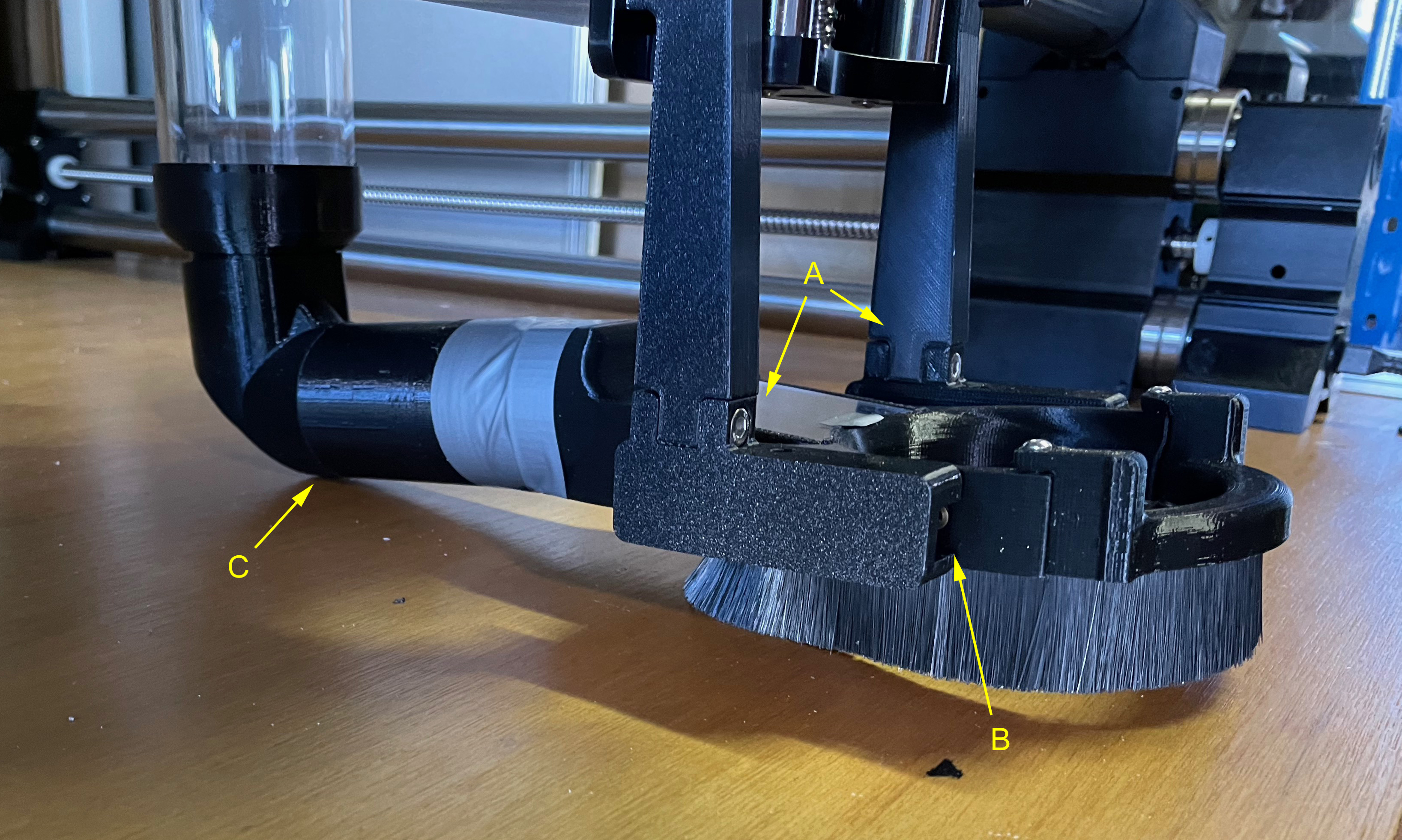
At “A” you can see the bolt head where the two parts of
the mounting arms are fixed together: this join is loose which
contributes to the back of the shoe dragging on the deck. “B” is
the slots where the shoe slides fit in and they are loose too.
You
can see the sag at “C” and the duct tape. That’s temporary.
I bought a pair of mini drawer rails to mount the arms to the carriage.
This
is still not ideal but it is better than it was.
I
want dust shielding for the mini rails. Not sure exactly how but I
will work something out.
mini
rails test fitted to the carriage.
They
don’t need to be perfect since the rails will not be moving when
the machine is operating but it is still important.
Here
is a diagram of my idea for mounting the dust shoe on the rails.
The
arms need some sort of locking mechanism that allows adjustment.
I
would like to have springs in there too – or some sort of friction
brake so that when it hits something it will move up and not break.
Well, that’s the theory.
This
is all good but there is also a serious space limitation that it
needs to fit in since adding to the width of the carriage will cut
down on the working area of the machine.
I
might 3D model the whole carriage so that I can design the rail
covers and other bits since it is a narrow area and there is a lot of
bits to fit in.
Thought
some more about shoe drag and came up with this: the arm that
holds up the hose should be sprung so that there is almost no weight
on the back of the shoe: then the shoe will be just fine and the
adjustment problem disappears. This hose arm also needs to provide
pivoting for the hose but I think both those things can be achieved
in one device.
I
still need to finish the shoe mount and add a position setting widget
but this will solve a lot of the problems.
The
hose is nearly touching the back wall at most rear position so the
hose will need to curve forward before it goes back: moving directly
back with the carriage at the far right will cause maximum curving of
the hose.
----------------------------------
A
change of plans
I
changed my plans for the dust shoe mounting as they were just too
complex and
as soon as things get dirty those drawer slides would have gummed up.
As
this part of the project had stalled I dropped all of the fancy stuff
- and since I now have a really good 3D printer (Plug here for the
BAMBU LAB X1 Carbon!) I designed a new mounting arm and got it
right on the second iteration ( I’m getting better at it now, the
first couple of 3D printed parts I designed took five or six tries )
Printed
and test fitted them, yup, all looking good. YAY!!!! Finally.
Also
printed new knobs for the Dust Shoe mount and fitted them to the new
mount arms. All is good so far, next up is making a new part to
extend the tube running back from the shoe to the vertical tube.
This
is the CAD pic of the new shoe mount in Blender. This is the inside
face, the outside is flat.
I
have no idea how the old ones were supposed to work - with the 80mm
spindle mount installed they won’t fit. Mine has a cutout to allow
the spindle mount to get past, the bolt holes are correctly aligned
and the knobs on the bolts are shaped to avoid hitting too. The are
designed to fit on Hex head M4 SS bolts. I used the same magnetic
locking system as both Onefinity and PWN – 6mm dia x 4mm magnets. I used four bolts rather than two to make things stronger since the big issue here is the load on the the back of the dust shoe.
---------------------------------------
Here
is the new setup. I used the clamping plates ( metal plates that run
in the back of the vertical slots) from both the original and the PWN
CNC mountings so that there are four bolts holding it on.
The
shoe slides bolted to the PWN shoe itself that slot into the arms
were too narrow and slopped around so I glued some ABS sheet on and
filed it down until it was tight in the shoe mounts.
Below
is the pic of the shoe installed showing the mounting arms and knobs.
You
can also see in the second pic below my 3D printed side screen mounts with 3mm clear plex
screens, the Estop button fitted and the white box under the bench is
the power meter so I can see what sort of current the whole thing
will pull.
There
is also a small LCD above the Estop that gives a temperature reading
for the cooling water tank.
. . . . . . and this is where I got to just about the same time Onefinity announced the Elite Series upgrade kit.
The control panel is finished, the lights work, most of the fabrication is done but there are still a few things to finish such as getting all of the limit sensors mounted - I was making my own because I really wanted them and they didn't come in the box. . .
. . . but I was still having problems - mounting the limit switches on the Z axis was one, but the software was a much bigger one: I do not want to get into coding. The whole point of this machine is to be able to use it to make parts for other projects. It was not supposed to be a major project itself. Yeah, I know.
So I'm getting the Elite upgrade kit. It solves a lot of my concerns with the original unit namely the lack of limit switches and step counting - and perhaps more importantly, software improvements. . . . . .
I hope to use a lot of my exisitng parts but we'll see about that. The dust collecting bits should not change and if you want the STL for the better mounting arms just email me.
The biggest problem I can see with installing the Elite kit in my setup is that the X servo will stick out past the wall of my cabinet : I will need to make a new right side wall with a bulge in it for that. I have already figured out a way to fit the Y servos by adding a "bump" but they are not going to move. That bulge is not so easy.
I originally made a plywood cabinet to put the control boxes in but then learned from the Onefinity forums of troubles other folks were having due to RF interference, particularly with VFDs and unsheilded cables so I dropped that and bought a PC cabinet which I shored up with some sheetmetal to make a well shielded box.
So there it is, looks like it will be
early next year before I get it running but I am not in a big rush.
Better to do things right even if it takes longer.
I was going to do a Part 5 with all of the wiring but that wil need to be redone with the new system and cables.